← Back
Waterloo Rocketry
Waterloo Rocketry is The University of Waterloo's student lead rocket design team, of which I was a member throughout my degree from 2019 to 2024. Below are some of my notable contributions to the team which lead to our 2022 Spaceport America Cup entry and subsequent rocket designs. To read more about the team, detailed project reports and more see Waterloo Rocketry's website.
Kraken of the Sky (KotS) - Hybrid Rocket for the 2022 Spaceport America Cup
Team: Waterloo Rocketry, University of Waterloo
Role: Recovery System Design, Testing, and Implementation
Competition: Intercollegiate Rocket Engineering Competition (IREC) at the Spaceport America Cup (SAC)
Category: 30,000 ft Apogee, Student Researched and Developed (SRAD) Hybrid/Liquid Propulsion
Project Overview

Figure 1: Simplified rocket diagram
Kraken of the Sky (KotS) is a hybrid rocket developed by Waterloo Rocketry for the 2022 Spaceport America Cup. The rocket is powered by the Kismet engine, a nitrous oxide/hydroxyl-terminated polybutadiene (HTPB) hybrid propulsion system, and is the third iteration in the Kismet series, following Unexploded Ordnance (UXO, 2018) and Shark of the Sky (SotS, 2019).
Primary Mission Goals:
- Achieve an apogee of 26,000 ft ± 2,000 ft.
- Ensure a non-hazardous descent using a novel reefed parachute system.
Secondary Mission Goals:
- Collect data on the performance of radiation shielding materials against galactic cosmic rays during flight.
Key Contributions: Recovery System Design
As a member of the recovery team, I played a central role in the design, testing, and implementation of a two-stage reefed parachute system for KotS. The system was developed to address three partial recovery failures in previous competitions with Kismet series (e.g., Shark of the Sky, 2019), a two-parachute system was used for recovery, which resulted in hard landings. This system primarily consisted of:
- Drogue Parachute: Deployed at apogee to stabilize the rocket during the initial high-speed descent.
- Main Parachute: Deployed at a lower altitude (typically around 1,000-1,500 ft AGL) to slow the rocket for a safe landing.
While this system worked in principle, it introduced several challenges:
- Increased Weight: Two parachutes, along with their deployment mechanisms, added significant mass to the rocket.
- Complexity: The system required separate deployment events for the drogue and main parachutes, increasing the risk of failure.
- Space Constraints: Storing two parachutes and their associated hardware took up valuable space in the rocket’s airframe, limiting payload capacity.
Advantages of a Reefed Parachute System
The reefed parachute system used in Kraken of the Sky (KotS) addresses these challenges by combining the functions of the drogue and main parachutes into a single, multi-stage system.
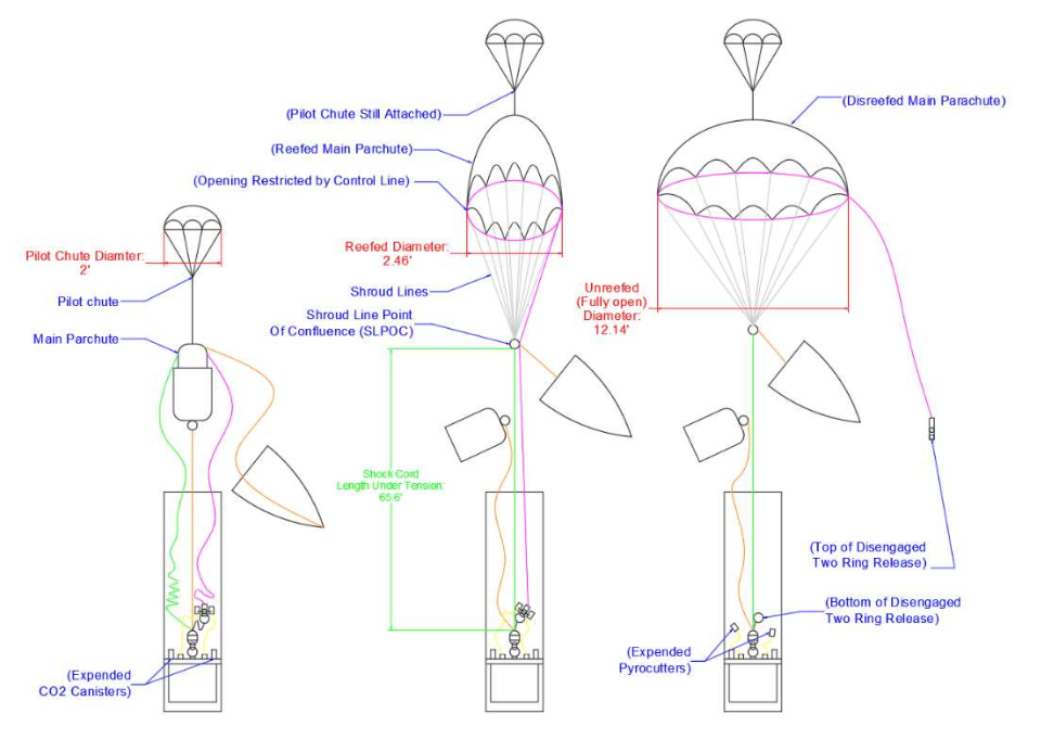
Figure 2: Step-by-step deployment squence diagram of the reefing system
Key advantages include:
Weight Reduction:
- A single parachute with a reefing mechanism is lighter than two separate parachutes, reducing the overall mass of the recovery system.
Space Efficiency:
- A reefed parachute takes up less space than two parachutes, freeing up room in the airframe for other components or payloads.
- The compact design simplifies packing and integration into the rocket.
Improved Performance:
- The reefed parachute provides better control over descent rates during both high-speed and low-speed phases, ensuring a stable and safe recovery.
- The system is highly tunable, allowing for precise adjustments to the reefing ratio and control line length to meet mission requirements. Electrically, the CAN bus consists of a differential wire pair for communications which connects the modules of the rocket in a tree topology, and is build around the PIC18 microcontroller. Some of these electronics sit on a single PCB in the recovery module.
System Overview
The recovery system for KotS is a two-stage, reefed parachute system designed to ensure a controlled descent and safe landing. The disreefing sequence is a critical phase of the recovery system, transitioning the parachute from a reefed (partially inflated) state to a fully inflated state to slow the rocket for a safe landing. At 1,500 ft AGL, the dual redundant altimeters (PerfectFlite StratoLogger and Featherweight Raven trigger the pyro-cutters, which sever a string holding the two-ring release mechanism. This mechanism consists of a small metal ring passed through a larger metal ring and tied back with the pyrocutter string. When the string is cut, the tension in the reefing control line is released, allowing the parachute skirt to fully expand. The control line, which runs through metal rings at the inner seam line of each parachute gore, is designed to constrict the parachute during the reefed phase. Once released, the parachute inflates fully, reducing the descent rate from 112 ft/s to 29.5 ft/s. The two-ring release mechanism was chosen to halve the load on the pyrocutter string and absorb the shock of initial inflation, preventing damage to the parachute or rocket. This design ensures a smooth and reliable transition, minimizing the risk of tangling or malfunction during disreefing.
The avionics system features a CAN bus, altimeters, a GPS tracking module, Live Telemetry Transmitter, Logger Board, and some other parts which are detailed in the full report. The CAN protocol was selected for it's ruggedness, strong noise immunity, and democratized protocol lended to good fault tolerance. Key components include:
Main Parachute:
A 12.4 ft diameter semi-elliptical parachute, sewn in-house using black and yellow ripstop nylon, based on Richard Nakka’s design. The parachute operates in two phases:
- Reefed Phase: Acts as a drogue, maintaining a descent rate of 112 ft/s.
- Disreefing Phase: At 1,500 ft AGL, redundant pyro-cutters release the reefing line, allowing the parachute to fully inflate and slow the rocket to a safe landing speed of 29.5 ft/s.
Pilot Parachute:
- A small 0.61 m flat parachute (bright orange) attached to the vent of the main parachute.
- Ensures the main parachute is pulled out of its bag and into the airstream during deployment.
Redundant Deployment Mechanisms:
- Dual Altimeters: PerfectFlite StratoLogger and Featherweight Raven 4 control the deployment sequence.
- CO2 Ejectors: Two 38 g CO2 canisters pressurize the parachute bay, breaking nylon shear pins (rated at 72 lbf) and separating the nosecone.
- Pyro-Cutters: Redundant pyro-cutters sever a string holding a two-ring release mechanism, which disengages the reefing control line and allows full parachute inflation.
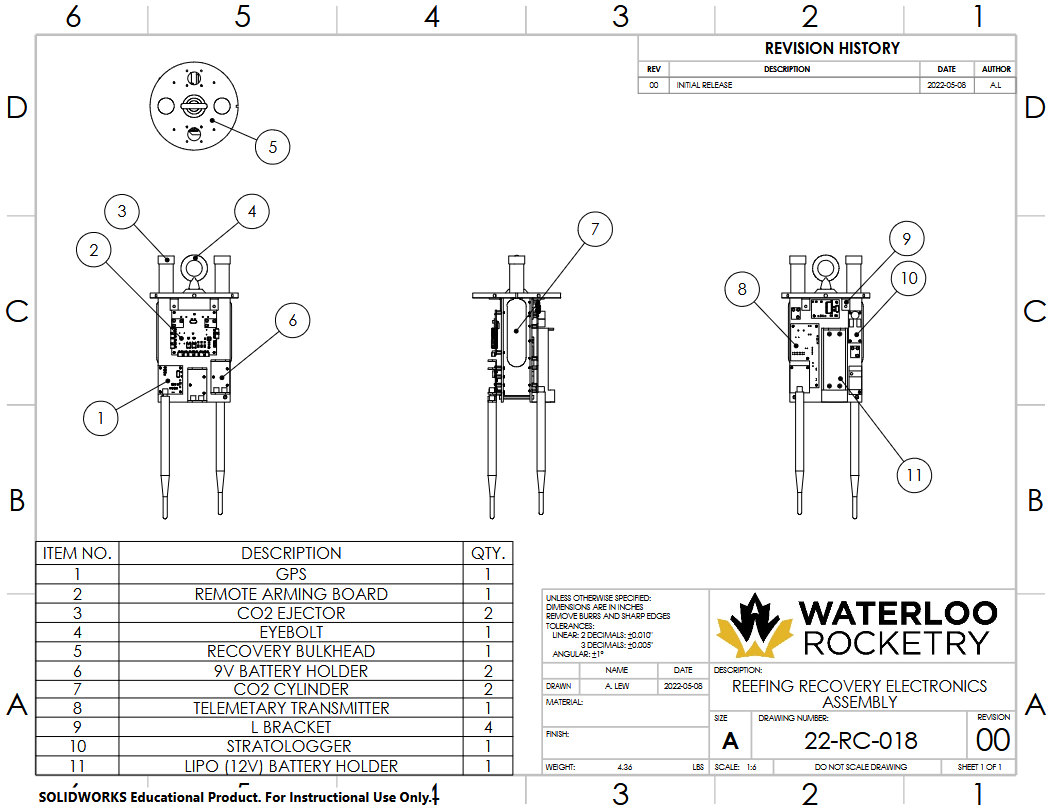
Figure 3: CAD rendering of the recovery electronics board
Reefing Mechanism:
- A single continuous control line, routed through metal rings at the parachute skirt, constricts the parachute during the reefed phase.
- The control line length was optimized through extensive ground-based parachute truck tests and wind tunnel testing to achieve the desired drag area and descent rate.
Recovery Section Bulkhead
- An aluminum bulkhead separates the recovery section from the rest of the rocket, housing the recovery electronics and deployment mechanisms.
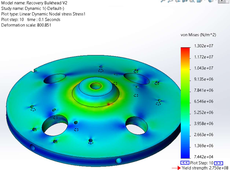
Figure 4: SolidWorks FEA analysis of recovery section bulkhead
Design Challenges and Solutions
Challenge: Hard Landings Under Drogue
- Previous rockets experienced hard landings due to insufficient drag during the reefed phase.
Solution:
- Designed a reefed parachute system with a precise control line length, optimized through iterative testing.
- Conducted parachute truck tests to generate a line length-to-drag area curve, ensuring the system met competition requirements (75-150 ft/s descent rate).
Challenge: Ensuring Redundancy and Reliability
- Deployment mechanisms in previous rockets had single points of failure.
Solution:
- Implemented dual CO2 ejectors and dual pyro-cutters for redundancy.
- Conducted ground testing to validate that a single CO2 ejector or pyrocutter could successfully deploy the system.
Challenge: Shock Loading During Disreefing
- The rapid deceleration during disreefing posed a risk of damaging the rocket or tangling the parachute lines.
Solution:
- Designed a two-ring release mechanism to halve the load on the pyrocutter string and absorb shock during disreefing.
- Conducted shock loading analysis to ensure the system could handle the forces experienced during deployment.
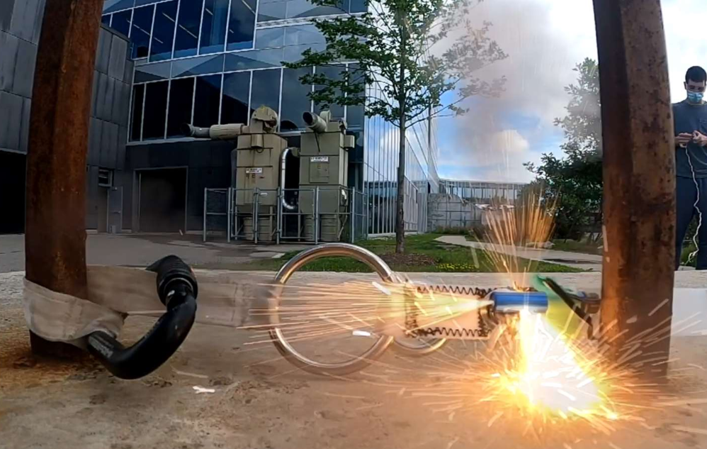
Figure 5: Pyro-cutter testing for reefing control line release
Testing and Validation
The recovery system underwent extensive testing to validate its performance and reliability. Parachute truck tests were conducted to evaluate different reefing concepts, including skirt reefing, vent reefing, and control line skirt reefing. These tests involved towing a scaled parachute behind a vehicle at varying speeds to simulate descent conditions. The goal was to determine the optimal control line length and reefing ratio to achieve the desired drag area and descent rate. Through iterative testing, a single continuous control line tied to one point and routed through metal rings at the skirt was selected for its simplicity, consistent shape, and resistance to tangling. Additionally, wind tunnel testing was performed to validate the parachute’s performance under controlled airflow conditions, confirming its ability to maintain a stable descent rate during both reefed and disreefed phases. Ground deployment tests simulated the full recovery sequence, including nosecone separation, parachute deployment, and disreefing. These tests verified the functionality of the CO2 ejectors, pyro-cutters, and two-ring release mechanism, ensuring redundancy and reliability. Shock loading analysis was also conducted to ensure the system could handle the forces experienced during deployment and disreefing. This rigorous testing process ensured the recovery system met competition requirements and could perform reliably under real-world conditions.
Parachute Truck Tests:
- Scaled tests were performed to evaluate different reefing concepts, including skirt reefing, vent reefing, and control line skirt reefing.
- A single continuous control line tied to one point and routed through metal rings at the skirt was selected for its simplicity, consistent shape, and resistance to tangling.
Wind Tunnel Testing:
- Validated the drag area and performance of the reefed parachute under controlled conditions.
- Confirmed the parachute’s ability to maintain a stable descent rate during both reefed and disreefed phases. Detailed measurements such as wind speed over time and load on attachment point over time were recorded
Ground Deployment Tests:
- Simulated the full deployment sequence, including nosecone separation, parachute deployment, and disreefing.
- Verified the functionality of the CO2 ejectors, pyro-cutters, and two-ring release mechanism.
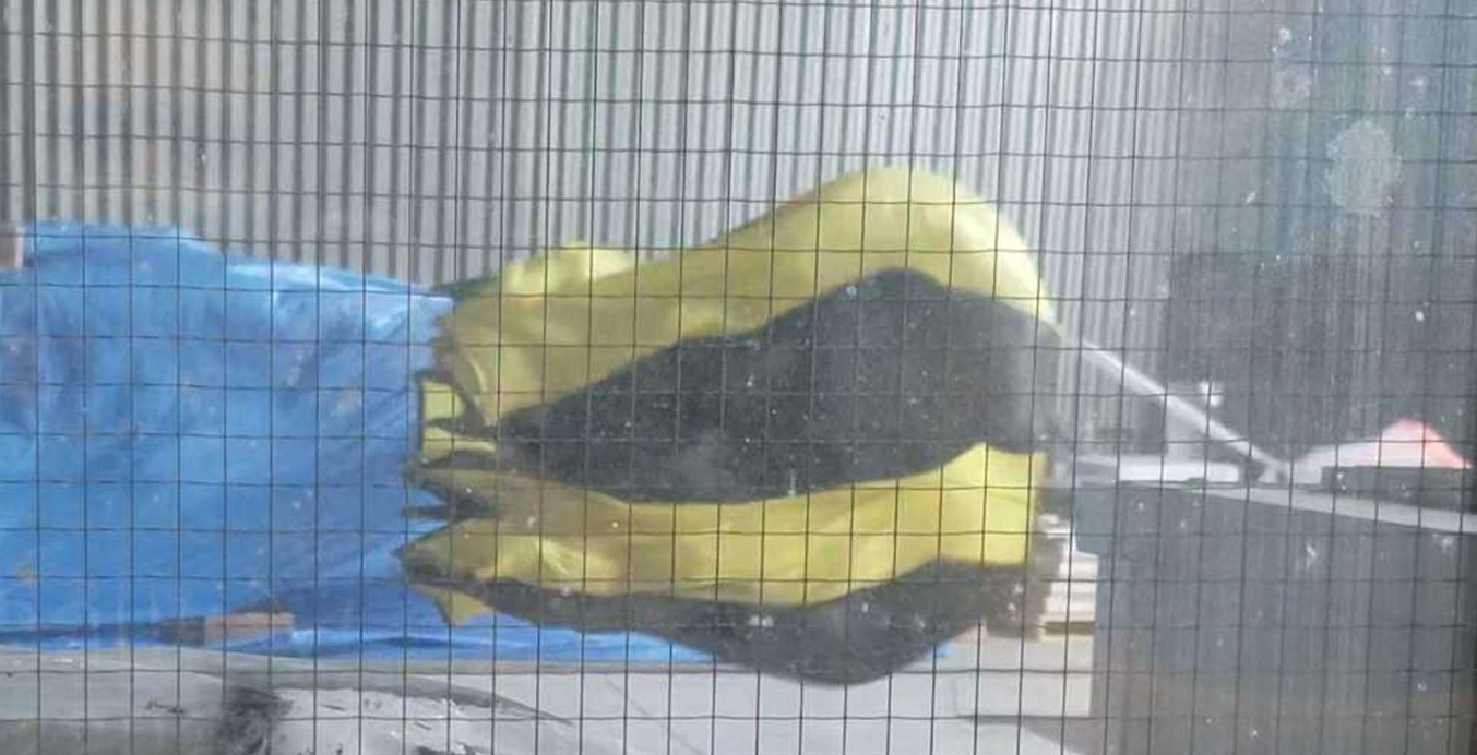
Figure 6: Wind tunnel testing of reefed parachute
Impact and Outcomes
- Successfully designed and implemented a reliable recovery system, addressing previous failures and ensuring a safe descent for KotS.
- Contributed to the team’s goal of reaching a 26,000 ft apogee and collecting valuable scientific data on radiation shielding materials.
- Gained hands-on experience in systems engineering, parachute design, and testing methodologies.